
The compatibility checker tells you whether your parts will work together. Topology warnings tell you how they're working together — and sometimes, why the answer is "not as well as you'd expect."
These warnings don't mean your build is broken. They mean something is happening inside your system that's worth understanding before you buy. This guide explains each one in plain language: what's causing it, whether it matters for your specific build, and what you can do about it.
What PCIe Lanes Actually Are
Every component that plugs into a PCIe slot on your motherboard communicates through lanes — high-speed data pathways between that component and the rest of the system. The number after the "x" in a slot name is the lane count: a PCIe x16 slot has 16 lanes, an x4 slot has 4 lanes, an x1 slot has 1.
More lanes means more bandwidth — the capacity for data to move faster. A GPU saturating its PCIe connection needs all 16 lanes. An NVMe expansion card with four M.2 drives needs at least 4 lanes (one per drive, if there's no switch chip). A Wi-Fi card needs only 1.
Lanes are a finite resource. Your CPU provides a fixed number directly, your chipset adds more, and your motherboard determines how they're distributed across slots. Once they're allocated, that's what you have.
Where Lanes Come From
Lanes on your motherboard come from one of two places: the CPU or the chipset.
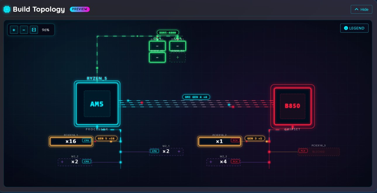
CPU-routed lanes connect directly to the processor. They're the fastest path — data travels straight from the component to the CPU without going through any intermediate hardware. Your primary GPU slot always uses CPU lanes for this reason. On a modern desktop platform, the CPU typically provides 16–28 PCIe lanes of its own.
Chipset-routed lanes go through the motherboard's chipset first. The chipset then connects to the CPU through a link called the DMI (Direct Media Interface). This adds a small layer of indirection — and more importantly, all chipset-routed devices share that single DMI link to the CPU. Secondary GPU slots, most M.2 slots, and all USB and SATA controllers typically run through the chipset.
The topology panel in RigSync shows which source each slot uses. CPU-routed slots sit closer to the CPU node in the diagram; chipset-routed slots pass through the chipset node. When a component gets pushed from a CPU slot to a chipset slot — because a GPU claimed the CPU lanes first — you see that movement in real time.
PCIe Generations
PCIe has gone through several generations. Each one roughly doubles the bandwidth per lane compared to the previous:
| Generation | Bandwidth per lane | x4 total | x16 total |
|---|---|---|---|
| PCIe 3.0 | ~1 GB/s | ~4 GB/s | ~16 GB/s |
| PCIe 4.0 | ~2 GB/s | ~8 GB/s | ~32 GB/s |
| PCIe 5.0 | ~4 GB/s | ~16 GB/s | ~64 GB/s |
The catch: the effective generation is the lowest of what the slot supports, what the CPU supports, and what the device itself supports. A PCIe 5 NVMe drive in a PCIe 4 M.2 slot runs at PCIe 4 speeds. A PCIe 4 GPU in a PCIe 5 slot from a PCIe 3 CPU runs at PCIe 3 speeds. Generation and lane width both matter — and topology warnings check both.
GPU and Expansion Card Bandwidth Reduction
What the warning says: Your GPU or expansion card is running at fewer lanes or a lower PCIe generation than it was designed for.
This happens when a component ends up in a slot that can't fully service it — either because the slot's physical lane count is lower than what the device expects (x8 instead of x16), or because the CPU or motherboard limits the slot to an older PCIe generation.
Does it matter?
For GPUs in gaming: usually not much. Moving from x16 to x8 costs less than 3% gaming performance for most cards, because the GPU is the bottleneck long before the PCIe bus is. The warning appears because there's technically a loss — but for most gaming builds, it's not actionable.
For NVMe expansion cards and high-bandwidth workstation hardware: it matters more. A card designed for PCIe 4 x4 running at PCIe 3 x4 loses roughly half its potential throughput. If you're running professional NVMe drives on that card, you'll feel it.
The warning tells you the exact bandwidth loss percentage so you can judge for your specific use case. A [TOPO_INFO] means the loss is under 50% — context, not a problem. A [TOPO_WARNING] means it's 50% or more — worth addressing if performance matters.
What to do: Check which component is limiting the slot (the warning identifies the CPU or motherboard specifically). A CPU upgrade or slot reassignment may resolve it.
M.2 Slot Downshift
What the warning says: Your NVMe drive is running at a lower PCIe generation than it's capable of, because of a CPU-specific limitation on that M.2 slot.
Some CPUs don't fully support the PCIe generation that a motherboard's M.2 slots are rated for. The slot is physically fine. The drive is physically fine. But when that specific CPU is installed, the slot drops from PCIe 4 to PCIe 3, for example. The warning fires when the installed drive is rated higher than what the CPU allows.
Does it matter?
For typical consumer NVMe drives: the sequential speed difference between PCIe 3 and PCIe 4 is real (roughly 3500 MB/s vs 7000 MB/s rated) but day-to-day tasks rarely saturate either. Boot times, application launches, and file transfers under a few gigabytes won't feel meaningfully different.
For large file work — video editing, large data sets, frequent big transfers — the difference is noticeable.
What to do: If the speed matters for your workload, check whether a different CPU in the same platform fully supports that slot. If you're using a CPU that partially limits M.2 generation, prioritize your fastest drives for slots that get full CPU support.
A second variant of this warning fires when the CPU changes the physical form factor a slot accepts — some slots only support shorter M.2 drives when a specific CPU is installed. That one is an error, not just a performance note.
Slot Conflicts and Lane Sharing
What the warning says: Installing a component in one slot has disabled or reduced bandwidth to another slot.
PCIe slots share lanes on the motherboard. This is by design — motherboard manufacturers route lane sharing explicitly, and the sharing rules are documented in the manual. But most users never read the manual.
Common examples:
- Installing a GPU in slot 1 disables M.2 slot 2 (they share CPU lanes)
- Installing a card in a PCIe x4 slot reduces an adjacent x16 slot to x8
- Populating a SATA port disables a specific PCIe slot (they share chipset bandwidth)
The topology panel shows disabled slots in a flagged state and names the component that caused it. The warning text tells you both which slot was affected and which component triggered it.
Does it matter?
If the disabled slot has something installed in it: yes, that device can no longer operate. That's an error. Remove one component or choose a different slot.
If the disabled slot is empty: it's informational. The slot is unavailable for future use, which matters if you planned to add more storage or a card later.
What to do: Slot conflict rules are fixed by the motherboard. If you need both slots active simultaneously, the only options are reassigning components to slots that don't share lanes, or choosing a motherboard with more independent lane paths.
Chipset Uplink Saturation
What the warning says: The combined bandwidth demand of your chipset-routed devices significantly exceeds the DMI uplink from the chipset to the CPU.
Think of the DMI link like a single shared highway between the chipset and the CPU. Every chipset-routed device — secondary GPU slots, chipset M.2 slots, SATA ports, USB controllers — shares that road. It has a fixed capacity. Add enough high-bandwidth devices and they collectively want more than the road can carry.
The warning only fires when the theoretical combined peak significantly exceeds the uplink — because most workloads don't saturate all devices simultaneously. It's a heads-up that under simultaneous heavy I/O across multiple devices, you may see throughput limits.
Does it matter?
For gaming builds: almost never. A GPU in a CPU slot plus a few SATA drives and chipset M.2 slots will never saturate the DMI link in practice.
For workstation builds with multiple high-speed NVMe drives in chipset slots plus a chipset-routed expansion card: it can matter under sustained parallel I/O — video capture to one drive while reading footage from another while exporting.
What to do: Move the most bandwidth-intensive component (typically the primary NVMe drive) to a CPU-routed slot. CPU-routed devices don't count against the chipset uplink.
PCIe Bifurcation
What the warning says: Your NVMe expansion card requires bifurcation support that the assigned slot doesn't provide, or requires a CPU generation that doesn't support it on this board.
Bifurcation is the ability to split one wide PCIe slot into multiple independent narrower connections. An x16 slot with x4x4x4x4 bifurcation can act as four independent x4 connections simultaneously — which is exactly what a four-drive NVMe adapter without a PLX switch needs.
Not all slots support bifurcation. Those that do often require a specific CPU generation to unlock it. The motherboard controls this in firmware, and the rules vary by board and chipset.
Cards with a PLX switch (or similar multiplexer) don't need bifurcation — the switch chip handles the lane splitting internally, in hardware, regardless of what the slot supports. If your card has a PLX chip, this warning won't fire.
Does it matter?
Yes, always. If your card needs bifurcation and the slot doesn't support it, only the first M.2 slot on the card will be accessible. The remaining drives won't appear to the system. This is a real failure mode, not a performance concern.
What to do: Check whether another slot on your board supports the required bifurcation mode. If none do, choose a card with a PLX switch — it works in any slot with sufficient lanes, regardless of bifurcation support.
Physical Slot Blocking and Board Edge Extension
These warnings live in the compatibility panel rather than the topology panel, but they're worth covering here since they relate to PCIe slot layout.
Physical slot blocking — Wide GPUs (2.5-slot, 3-slot) cover the slot openings immediately below them on the board. Any component that needs one of those covered slots can't be physically installed alongside the wide GPU. The topology panel shows blocked slots in a distinct state; the compatibility panel tells you which GPU caused the block.
Board edge extension — When a GPU is placed in a slot close to the bottom of the board and its physical body extends past the last slot, the compatibility checker flags it. This is most common on dual-GPU setups where the second GPU ends up lower on the board than expected after the first GPU claims the primary slot.
Both are purely physical — they have nothing to do with electrical lanes. A slot can be electrically available but physically inaccessible because of card bodies in adjacent positions.
A Note on Severity
Topology warnings come in two levels:
[TOPO_WARNING] — Something is meaningfully wrong. Bifurcation failure, a device that can't operate, bandwidth loss over 50%, or a physical block on an occupied slot.
[TOPO_INFO] — Something worth knowing but not necessarily acting on. A minor lane reduction, a chipset saturation approaching but not dramatically exceeding the uplink, or a slot conflict affecting an empty slot.
In general: fix the warnings, consider the infos. If you understand the info and it doesn't affect your use case, you can ignore it.
Further Reading
- What's New on RigSync - July 2026 — Full announcement of the topology system
- Getting Started with RigSync — Overview of the Component Browser and compatibility system
- Component Browser → — See the topology panel in action
Comments (0)
No comments yet. Be the first to share your thoughts!